 340 KATANA A-CNC-R / Katana
 It's no longer on sale
| mm | 0° | 45° | 60° | -45° | -60° |  |
 |
|---|---|---|---|---|---|---|---|
 |
350 | 350 | 230 | x | x | x | x |
 |
250* | 180* | 130* | x | x | x | x |
 |
500x340 | 400x340 | 220x340 | x | x | 500x340 |
 |
 |
 |
 |
 |
|---|---|---|---|---|
| 3x400V | 3,0 | 20-100 | 4780x34x1,1 | 2050 |
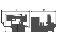
| Lmin | Lmax | Bmin | Bmax | Hmin | Hmax | V |
|---|---|---|---|---|---|---|
| 2900 | 3050 | 2500 | 2900 | 1820 | 2050 | 800 |
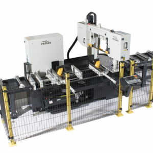
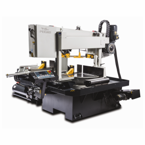
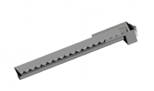
It is a highly efficient automatic hydraulically controlled band-saw with multiple material feed. Feeder movements using a ball screw. The arm as well as the vice movements using hydraulic cylinders.
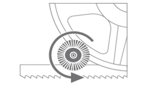
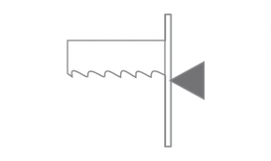
Suitable for perpendicular cuts in automatic mode, angular cuts in semi-automatic mode It enables angle cuts to the right (0 - 60 grades). Angles setting is manual. Machine uses the GTO function (automatic movement of the feeder to set position).
The band saw machine suitable for cutting of steel constructions and profiles with a longstep feeder L=1000mm (one feeder step). The machine is constructed for automatic cutting of long bars. Whenn the machine is cutting Automatic programm with angle cuts and with lenghts shorter thann 500mm, the machine automatically interrupts the automatic cycle and is waiting.
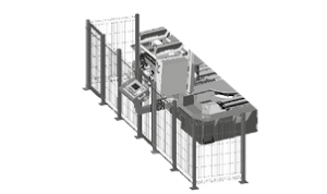
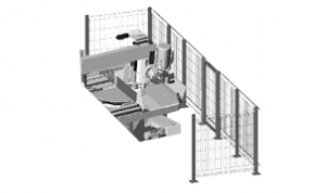
It is suitable for serial production and thanks to its robust construction enables to cut wide range of materials including stainless steels and tool steels both profiles and full materials.
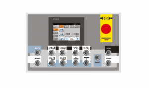
Control systém:
Machine is equipped with the control, programmable PLC MITSUBISHI FX5U. Blade drive as well as the feeder movements afe fully controlled by the frequency inverters MITSUBISHI.
The coloured touch screen MITSUBISHI GT 2104 enables easy communication with an operator. It shows working conditions (blade speed, moving to the cut, cutting parameters etc.)
The lenght and quantity are set by the control panel. Machine will optimize all next calculations itself. It is possible to set 15 different programms for quick lenghts setting.
Feeder drive: frequency inverter, electromotor + encoder, gear using belt, ball screw, nut of ball screw placed on feeder.
Machine enables semi-automatic and automatic mode (all movements are controlled automatically).
Regulation of the shift speed (bow movement to the cut) is manual using a throttle valve laces beside the control panel. Automatical (safety) of the shift speed PEGAS BRP: Exceeding of set loading (in amperes) will stop the shift speed.
The controlling panel is equipped with a safety button, which stops the saw, and another two buttons for turning it on. Buttons for machine movements handling are parts of high quality control keyboard.
Construction:
The machine is constructionaly designed in that way, so that it corresponds to extreme exertions in productive conditions. A robust construction of machine includes vice allows to take advantage of bimetal blades maximally.
The arm of the machine is robust, heavy weldment and it is designed so that a toughtness and a precision of cut was ensured.
The arm moves along two columns using a four row linear leading with a high loading capacity. Arm movement using two hydraulic cylinders.
Drive pulley and tighten pulley are both metal castings.
T-bar - device used for upper possition of the arm. T-bar moves along linear leading, controlled by micro-switch
Upper position automatically using of incremental sensor with magnetic tape for measuring of a position above material. Arm position control is numeric setting of it into cutting programm.
Down position using adjusting stop and microswitch. After reaching of bottom position arm goes to upper position automatically.
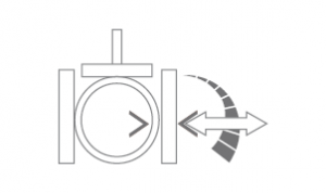
The main vice - iron casting with massive jaw for material fixing
Casting jaws of the main vice move in leading using hydraulic cylinder. One jaw is longstroke (the movement by longstroke hydraulic cylinder), one is fixed.
Regulation valves for setting a vice pressure in hydraulic system.
Very rigid feeder with the feeding step 1000 mm moves along the linear leading
Feeder drive: frequency inverter, electromotor + encoder, gear using belt, ball screw, nut of ball screw placed on feeder.
The feeder placed ot a linear leading using prestressed carriages
Feeder position is controled by rotatory encoder. An operator choose one of three feeder speeds. It uses micro speed for reaching the correct position. Acceleration and decelerate movements are controlled by a frequency invertor.
Indication of material in the feeder: optic sensor - it notices that there is a material in the feeder. If there is no material in the feeder, the signal reflects on the glass that is situated on movable jaw and it goes back to the sensor. The machine stops feeding and waits for another bar.
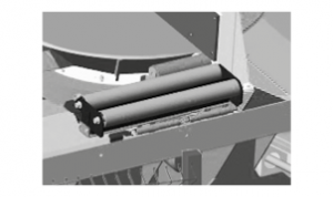
Material moved to the cut zone is suported by 4 cylinders. Three of them are movable, one os stationary. Moving cylinders help to move the material to the optimal position.
The feeder vice - massive casting, a jaw enables safe material clamping
The movement of feeder vice along of leading using long stroke hydraulic cylinder.The vicehas floating fixation to eliminate a crooked material.
Turn table is massive weldment. It is placed and fixed on base using massive shaft and precision double row bearings.
Bow rotation to angular cuts is manualy as well as angle seting.
Angles (degrees are shown at the touch screen MITSUBISHI. Angle indication using incremental sensor and a magnetic tape.
Basic equipment of machine:
The blade leading in guides with hardmetal plates and leading bearings.
The blade is 4 grades sloped regarding the level of the vice => higher performance when cutting, profiles, longer bladelife, higher performance when cutting full materials.
There is a guide situated on the firm beam on the drive side. On the tightening side there is the guide situated on the moving beam.
The guide beams of the blade are adjustable in the whole working range. Guide movement is manual, its fixation is manual too.
The guide beam is moving along of linear leading (1 rail, 2 carriages) with high loading capacity
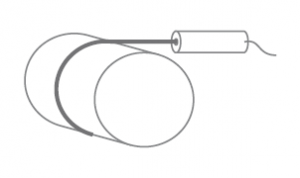
The saw-band is equipped with a covers, which protect the operator from millings and cutting emulsion.
Manuall tightening of band. Optional: Hydraulic tightening of band.
Automatic indication of blade tension using micro switch.
A passive driven cleaning brush for perfect cleaning and function of blade.
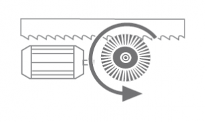
Drive of blade is solved by worm gear box with maintenanceless oil filling. Three-phases electromotor with double winding, with a frequency converter for a fluent regulation of the blade speed from 20 to 100 m/min. Sturdy flange with shaft. Termoprotection of engine.
The cooling system for emulsion, leaded to the guides of the blade and by LocLine system directly to the cut groove.
Massive base with a tank for chips. Base is designed for manipulation manipulation with machine by any hight lift truck or by crane.
Indication of blade tightening and opening of the cover.
Controlling 24 V.
Machine is equipped with hydraulic system which controles all functions of the machine.
Basic equipment of machine:
Two massive cylinders for support of cutted materials. They are moving, so they are not a hinderance of arm turning. Theirs movements are along linear leading
Spray gun for swarfs washing off
Lighting of workink space.
Band saw blade.
Set of spanners for common service.
Manual instructions in eletronic form (CD).
Operating cycle:
After start of the cutting machine clamp the vices, the cut will be done by ste speed. After reaching the down position, arm is going up automaticaly. Feeder move with next peace to the cuting zone (feeder vice is going between zero position and set position (length of cutted peaces). Main vice clamps the material, feeder vice is opening and moves to feed next peace. Whole cyclus starts again. Operator puts new material and remove cutted peaces only. It is possible change blade speed as well as shift speed during the cut.
| Code | Description | Type | |
|---|---|---|---|
 | MITSUBISHI NC | Controling system MITSUBISHI with touchscreen. | ST |
 | F | Motor and frequency converter for a fluent change of the circumferential speed of the blade. | ST |
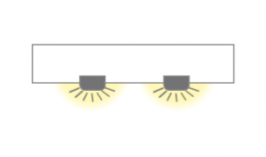 | LED | Lighting of workink space. | ST |
| 340-NPH | Hydraulic tension of band. | OP | |
 | 340-VTT | Worm chip extractor for long chips (stainless-chips), includedd 1 pc of BOX-TRI. | OP |
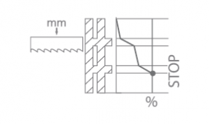 | PEGAS-BRP | Electronical regulation of the down-shift. | ST |
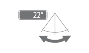 | PUD | Digital indicator of adjusted angle | ST |
 | PCK | Cleaning brush of blade, driven passively (driven by pulley). | ST |
 | 340-ECK | Cleaning brush of blade driven actively by motor. | OP |
 | 340-PVZ | Supportin cylinder, situated on the base of the saw on the linear feeding - outpud side. | ST |
 | RTS-A | Regulation press of vice – set of 2 pcs for bothvices. | ST |
 | 340-IRP | Down shift speed indication value on the display of controling system (mm/min ). | ST |
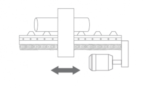 | 340-BSF | Feeder moving using linear leading, ball screw and servo motor. | ST |
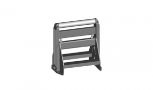
 | 340-RNT | Frontal safety cover. | ST |
 | 340-RNT-Z | Rear safety cover. | OP |
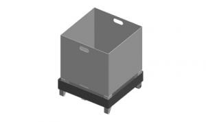 | BOX-PCS | Box for cutted pieces with emulsion draining to the waterproof tank. | O |
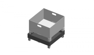 | BOX-TRI | Box for the chips with emulsion draining to the waterproof tank. | O |
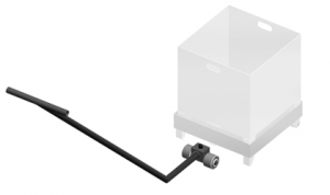 | BOX-TAH | Tool for manipulation with BOX-PCS and BOX-TRI. | O |
| 340-HP-A | Hydraulic upper clamping tighten the material in vertical sense by the short step hydraulic cylinder connected with the cylinder of the main vice. Set of 2 pcs. | OP | |
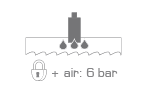 | MINI LUBE | Wasteless lubricating system, instead of emulsion cooling, specially for cutting profiles and non-ferrous metals, neccessary supply of pressed air 6 Atm. | OP |
 | LASER LINE | Laser indicator of cut position. | OP |
| VD-2000/520/60/6 | O | ||
| VD-2000/520/60/10 | O | ||
 | VD-V-520 | Aditional cylinder, lenght 520 mm. | O |
 | VD-VB-190 | Vertical cylinder 190 mm assamblen od the VD1. | O |
 | VD-BL | Support from vertical side - bearing. Assambled on VD1 | O |
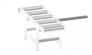
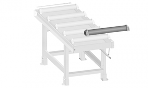
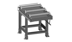 | RDT 1000/520 | Robust roller conveyor with coolant gutter. Width of cylinders 520 mm, length 1000 mm, 3 rollers, it is possible to put them for RDP or RDZ, load capacity 2100 kg/m. | O |
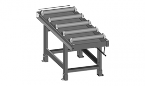 | RDT 2000/520 | Robust roller conveyor with coolant gutter. Length 2000 mm, width of cylinders 520 mm, 5 rollers, load capacity 2100 kg/m. | O |
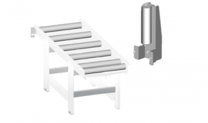
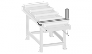 | 360-RB | Side support fixed cylinder, height 200 mm, diameter 67 mm including support - length 520 mm, monted to the convoyer RDT. INPOSIBLE ASSAMBLE ON VD1 ROLLERTABLES. | O |
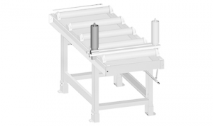 | 360-RBS | Side movable cylinder for preparation of bundles, adjustable, height 200 mm, diameter 67 mm it is avalible only with RB. INPOSIBLE ASSAMBLE ON VD1 ROLLERTABLES. | O |
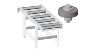
 | 360-RDH | Independent movable cylinder, adjustable height, capacity 700 kg. INPOSIBLE ASSAMBLE ON VD1 ROLLERTABLES. | O |
 | 360 V | Roller of roller table RDT put into gap. | O |
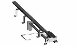 | OZP | Mechanical fixed stop with ruler and scale line 2 meters long. INPOSIBLE ASSAMBLE ON VD1 ROLLERTABLES. | O |
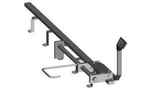 | OZP-D | Mechanical fixed stop with digital display 2 meters long. INPOSIBLE ASSAMBLE ON VD1 ROLLERTABLES. | O |
| 340-QPARTS-PCK | Set of wear and tear spare parts: | O | |
 | 340-NAV | Manual instruction – printed version. | O |
Tech. data NO241 are valid on 1.1.2024. Producer has the right to make changes of technical data.
Values contained on this page are only for information purposes. This information is not an offer and is not a public promise. This indicative offer does not give right to close a contract. The only guiding document for the contract is a valid price list.