 440x600 HORIZONTAL SHI / Horizont
 It's no longer on sale
| mm | 0° | 45° | 60° | -45° | -60° |  |
 |
|---|---|---|---|---|---|---|---|
 |
470 | 475 | 330 | 475 | 305 | x | x |
 |
250* | 180* | 130* | 180* | 130* | x | x |
 |
610x410 | 490x415 | 320x410 | 495x415 | 305x425 | 610x255 | 600x430 |
 |
 |
 |
 |
 |
|---|---|---|---|---|
| 3x400V | 4,0 | 20-100 | 6060x34x1,1 | 1685 |
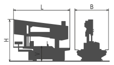
| Lmin | Lmax | Bmin | Bmax | Hmin | Hmax | V |
|---|---|---|---|---|---|---|
| 2950 | 3500 | 1760 | 1760 | 2150 | 2310 | 810 |
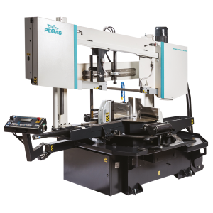
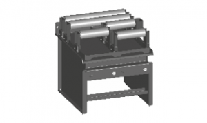
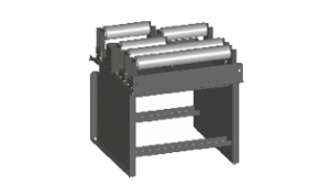
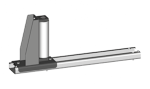
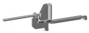
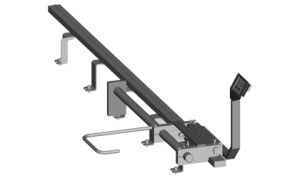
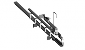
Semiautomatic, hydraulically manipulated two-column band saw machine.
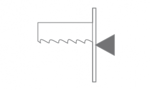
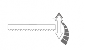
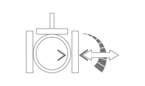
The band saw machine is designed for cutting in semiautomatic cycle perpendicularly as well as angularly. It enables angle cuts to the left (60 grades) and to the right (60 grades).
It is suitable for serial production and thanks to its robust construction enables to cut wide range of materials including stainless steels and tool steels both profiles and full materials.
Control systém:
- The Controler with PLC MITSUBISHI and features an automatic feed control BRP.
- Control panel MITSUBISHI as standard equipment. It uses touch display and PLC, which enable semi-automatic cutting (basic setting encluded) as well as communication with operator.
- Controler show lot of information about cutting proces on the display:
- Cutting cycle indication,
- indication BRP,
- indication – blade tightening,
- time of the cut,
- loading of blade in amperes,
- speed of the blade,
- cutting times measuring,
- list of error messages. - User´s setting:
- autostop of hydraulic unit
- mode of arm moving after end of the cut
- mode fadt moving of the arm
- mode time lag of shift speed
- mode blade moving
- mode jaw moving after cutting cycle finish
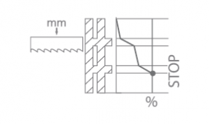
- diagnostic of inputs and outputs" - STOP function – cutting : it enables to stop cutting by pressing STOP button at any time. The Frame goes up with the running blade without opening the vice.
- Regulation of shaft speed (moving to cut) is manual and uses throttle valve placed beside control panel. Automatic (safety) regulation of shift speed PEGAS BRP. Principle: Machine will stop after exceeding set loading (defined in ampers).
- The ergonomical control panel is mounted on the movable console and its position does not depend on the turntable position at any angle. The control of the machine is optimalized with our control panel and the field of view is better for an operator. The control panel is equiped with mechanical buttons and digital display of the machine control system. Mechanical buttons controls basic saw movements (arm, vice, feeder and turntable movements) and cutting cycle start. The safety button is present on the panel aswell. All buttons are highly resistant in anti-vandal version.
Construction:
- The machine is constructionaly designed in that way, so that it corresponds to extreme exertions in productive conditions. A robust construction of machine includes vice allows to take advantage of bimetal blades maximally.
- The arm of the machine is robust, heavy weldment and it is designed so that a toughtness and a precision of cut was ensured.
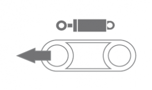
- The arm moves along two columns using a four row linear leading with a high loading capacity. Arm movement using two hydraulic cylinders.
- Drive pulley and tighten pulley are both metal castings.
- The arm uses sensor and magnetic tape for position evaluation above material. Upper working position of the arm is possible to set in control system.
- Down working position is set with adjustable mechanical stop and microswitch. Down working position of the arm is also possible to set in the saw control system. After reaching bottom working position the arm stops in the position set in the system.
- Main vice with divided jaw that clamps the material in front of as well as behind the cut. The jaws allow a safe grip.The optimalization of the chip movement through the fixed jaw directly to the chip extractor.
- Jaws of the main vice move in steel leading using hydraulic cylinder. One jaw is longstroke (the movement by longstroke hydraulic cylinder), one is fixed.
- Regulation valves for setting a vice pressure in hydraulic system.
- Turn table is massive weldment. Turn table for angular cutts with milled leading parts of base. Turn table enables comfortable claming of cutted material. Turning using hydr. cylinder and cog gearing.
- Hydraulic angle setting:
a) move with the arm using the button to needed angle ( fast speed/micro speed)
b) using RTO function (rotate to position) with automatic setting of needed angle arm position. - Hydraulic psition fixiation by a "lock"
- The angles indicated on the digital display on the control panel MITSUBISHI. Reading of angle by incremental sensor and magnetic tape.
Basic equipment of machine:
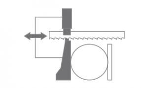
The blade leading in guides with hardmetal plates and leading bearings and along cast iron pulleys.- The blade is 7 grades sloped regarding the level of the vice => higher performance when cutting, profiles, longer bladelife, higher performance when cutting full materials.
- There is a guide situated on the firm beam on the drive side. On the tightening side there is the guide situated on the moving beam.
- The guide beams of the blade are adjustable in the whole working range. A giude moving is connected with a vice-jaw movement so that to achieve the minimum distance of the guide and material. That is why it is not neccessary to set the position manually.
- The guide beam of the blade is placed in linear rails (2 linear rails and 4 bearings) with high bearing capacity.
- The saw-band is equipped with a guard, which protects the operator from millings and cutting emulsion.
- Manuall tightening of band. Optional: Hydraulic tightening of band.
- Automatic indication of blade tension.
- A cleaning brush for perfect cleaning and function of blade, passive driven by pulley.
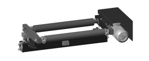
- Drive of machine is solved by worm gear box with maintenanceless oil filling. Three-phases electromotor with double winding, with a frequency converter for a fluent regulation of the blade speed from 20 to 100 m/min. Sturdy flange with shaft. Termoprotection of engine.
- The cooling system for emulsion, leaded to the guides of the blade and by LocLine system directly to the cut groove.
- Massive base with a tank for chips. Base is designed for manipulation manipulation with machine by pallet truck and also by any hight lift truck or by crane.
- Indication of blade tightening and opening of the cover.
- Controlling 24 V.
- Machine is equipped with hydraulic system which controles all functions of the machine. It pushes the arm to cut, pulls up the arm, opens and closes vices, turnins the turntable for angular cuts.
Basic equipment of machine:
- Spray gun for chip rinsing
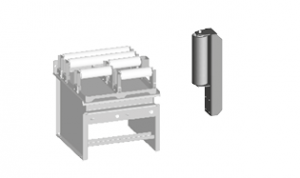
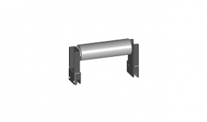
- Two massive cylinders support material to be cut. Movable by linear leading
- Lighting of workink space.
- Band saw blade.
- Set of spanners for common service.
- Manual instructions in eletronic form (CD).
Operating cycle:
After starting the machine, vices are clamped automatically, cut is made by selected cutting speed, in the end position microswitch is on, arm goes to selected upper position and vices open automatically. The operator only handles material.
| Code | Description | Type | |
|---|---|---|---|
| MITSUBISHI HMI 4,5" | Control system MITSUBISHI with display 4,5“ | ST | |
 | F | Motor and frequency converter for a fluent change of the circumferential speed of the blade. | ST |
 | PEGAS-BRP | Electronical regulation of the down-shift. | ST |
 | HPV | Solution of moving guides of band together with jaws of the vice. | ST |
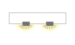 | LED | Lighting of workink space. | ST |
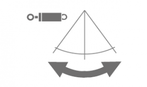 | PUH | Hydraulical side moving of bow with hydraulically locking of setting angle. | ST |
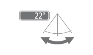 | PUD | Digital indicator of adjusted angle | ST |
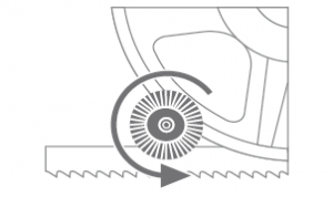 | PCK | Cleaning brush of blade, driven passively (driven by pulley). | ST |
 | 440x600-IRP | Down shift speed indication value on the display of controling system ( mm/min ) | ST |
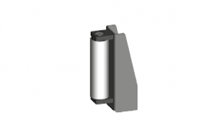
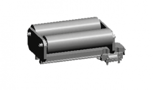 | 440x600-PVP | Supportin cylinder , situated on the base of the saw on the linear feeding - Inpout side. | ST |
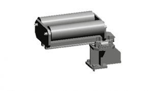 | 440x600-PVZ | Supportin cylinder , situated on the base of the saw on the linear feeding - outpud side. | ST |
 | RTR | Regulation press of arm. Cutting conditions optimalization (regulates force that push the blade to the material so this function increases blade lifespan). | ST |
 | RTS | Regulation press of vice. | ST |
 | 440x600-NPH | Hydraulic tension of band. | OP |
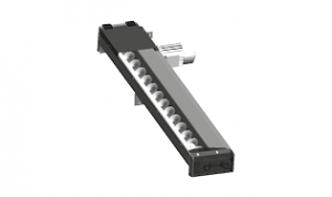 | 440x600-VTT | Worm chip extractor for long chips (stainless-chips), includedd 1 pc of BOX-TRI. | OP |
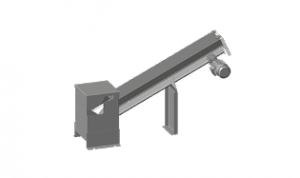 | 440x600-VTT-D | Additional chips extractor suitable for long swarfs. It enables transport of swarfs to 730 mm height. | OP |
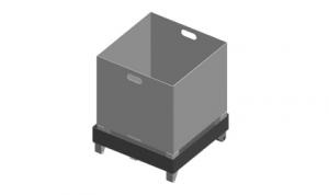 | BOX-PCS | Box for cutted pieces with emulsion draining to the waterproof tank. | O |
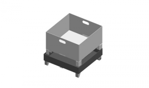 | BOX-TRI | Box for the chips with emulsion draining to the waterproof tank. | O |
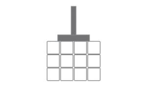
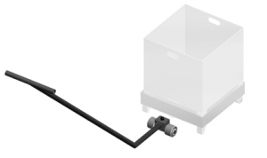 | BOX-TAH | Tool for manipulation with BOX-PCS and BOX-TRI. | O |
 | 440x600-HP | Hydraulic upper clamping tighten the material in vertical sense by the short step hydraulic cylinder connected with the cylinder of the main vice. | OP |
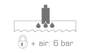 | MINI LUBE 27-34 | Wasteless lubricating system, instead of emulsion cooling, specially for cutting profiles and non-ferrous metals, necessary supply of pressed air 6 Atm. | OP |
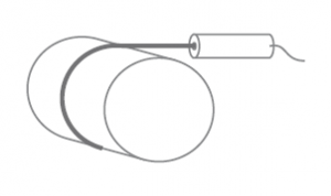 | LASER LINE | Laser indicator of cut position. | OP |
| 440-QPARTS | Set of easy worn away spare parts : | O | |
| 440-QPARTS 2 | O | ||
| 440-SET M42 | Set of 10 blades in M42 quality – with customer’s choice of teeth. 6060x34x1,1 | O | |
| 440-SET M51/10 | Set of 10 blades in M51 quality – with customer’s choice of teeth. 6060x34x1,1 | O | |
| 440x600-NAV | Manual instruction – printed version. | O | |
| PAL4 | Packing on the palette 1,5 m x 3,5 m. | O | |
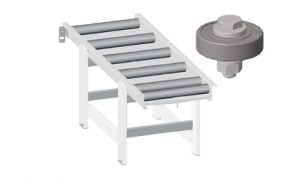
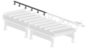
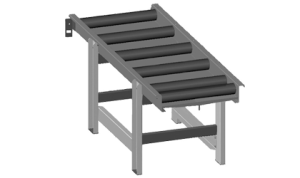 | VD-2000/620/89/6 | Input or output roller conveyor with a gutter which prevents leakage of emulsion on the floor. Length 2000 mm, width of cylinders 620 mm, capacity 350 kg/m. | O |
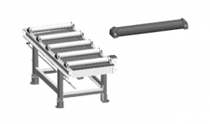
 | VD-V-620 | Aditional cylinder, lenght 620 mm. | O |
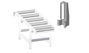 | VD-VB-190 | Vertical cylinder 190 mm assamblen od the VD1. | O |
 | VD-BL | Support from vertical side - bearing. Assambled on VD1 | O |
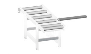
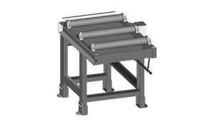 | RDT 1000/620 | Robust roller conveyor with coolant gutter. Length 1000 mm, width of cylinders 620 mm, 3 rollers, it is possible to put them for RDR or RDL, capacity 2500 kg/m. | O |
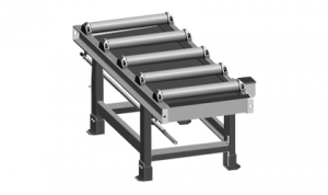 | RDT 2000/620 | Robust roller conveyor with coolant gutter. Length 2000 mm, width of cylinders 620 mm, 5 rollers, it is possible to put them for RDR or RDL ,capacity 2500 kg/m. | O |
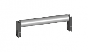
 | 440x600-RDP-800/620 | Input robust connecting conveyor that is neccesary for making angle cuts and for connection to RDT, RDM. Lenght 800 mm, width of cylinders 620 mm, 5 rollers, capacity 1700 kg/m. | O |
 | 440x600-RDZ-800/620 | Output robust connecting conveyor, there is a special shape for angle turning of the machine and for connection to RDT, RDM. Lenght 800 mm, width of cylinders 620 mm, 5 rollers, capacity 1700 kg/m. | O |
 | VZM-620 | The cylinder of rollertable, which is driven by electroengine, with 620 mm, is able to lift the material hydraulically above the level of other rollers. It is solution for later assembly to the standard rollertable RDT insta 2pcs of original cylinders. Control of the roller is independent on the controlling of the machine, the roller has its own controlling panel. | OP |
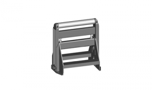
 | 500-RBR | Side support fixed cylinder, height 280 mm, diameter 87 mm with its own frame, mounted to roller tables RDT. | O |
 | 500-RBRS | Side adjustable roller, with its own steel frame, and with the movable leading 620 mm, fixed by 2 pcs of T-nuts. Height 280 mm, diameter 87 mm. | O |
 | 500-CSV | Hydraulical shift for the RBRS roller including assambly of electrical and hydraulical instalation. Possibile only with RBRS | OP |
 | 440x600 RB-RDP | Vertical side cylinder for roller table 440x600 RDP. | O |
 | 440x600 V-300-RDP | Additional cylinder for roller table RDP. Lenght 300 mm | O |
 | 440x600 V-620-RDP | Additional cylinder for roller table RDP. Lenght 600 mm | O |
 | V-620 | Roller of roller table RDT put into gap. | O |
 | 500-RDH | Independent movable cylinder, adjustable height, capacity 1000kg. | O |
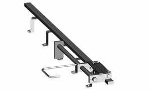 | OZP | Mechanical fixed stop with ruler and scale line 2 meters long. INPOSIBLE ASSAMBLE ON VD1 ROLLERTABLES. | O |
 | OZP-D | Mechanical fixed stop with digital display 2 meters long. INPOSIBLE ASSAMBLE ON VD1 ROLLERTABLES. | O |
 | OZS | Electromechanical stop working with RDM roller table. It has two contacts. When material switches the first contact, RDM slows down, after switching the second contact, RDM stops. Works only with OZS-L. | O |
 | OZS-D | Electromechanical stop working with RDM roller table. It has two contacts. When material switches on the first contact, RDM slows down, after switching on the second contact, RDM stops. | O |
| OZP-L-RDZ | Measuring system rail for OZP mounted on FIRST roller table. | O | |
| OZP-LE-RDZ | Measuring system rail for OZP mounted on FIRST AND EITHER LAST roller table. | O | |
| OZD-L-RDZ | Measuring system for OZD mounted on FIRST roller table. | O | |
| OZD-LE-RDZ | Measuring system for OZD mounted on FIRST AND EITHER LAST roller table. | O | |
| OZS-L-RDZ | Measuring system for OZS mounted on FIRST roller table. | O | |
| OZS-LE-RDZ | Measuring system for OZS mounted on FIRST AND EITHER LAST roller table. | O | |
| OZSD-L-RDZ | Measuring system for OZS-D mounted on FIRST roller table. | O | |
| OZSD-LE-RDZ | Measuring system for OZS-D mounted on FIRST AND EITHER LAST roller table. | O | |
| OZP-L 1000 | Measuring system rail for OZP mounted on 1 m roller table. | O | |
 | OZP-L 2000 | 2 meters long extension of OZP. | O |
| OZP-LE 1000 | Measuring system rail for OZP mounted on LAST 1 m roller table in the setup. | O | |
| OZP-LE 2000 | Measuring system rail for OZP mounted on LAST 2m roller table in the setup. | O | |
| OZD-L 1000 | Measuring system for OZD mounted on 1 m roller table. | O | |
 | OZD-L 2000 | 2 meters long extension of OZD. | O |
| OZD-LE 1000 | Measuring system for OZD mounted on LAST 1 m roller table in the setup. | O | |
| OZD-LE 2000 | Measuring system for OZD mounted on LAST 2 m roller table in the setup. | O | |
| OZS-L 1000 | Measuring system for OZS mounted on 1 m roller table. | O | |
| OZS-L 2000 | Measuring system for OZS mounted on 2 m roller table. | O | |
| OZS-LE 1000 | Measuring system for OZS mounted on LAST 1 m roller table in the setup. | O | |
| OZS-LE 2000 | Measuring system for OZS mounted on LAST 2 m roller table in the setup. | O | |
| OZSD-L 1000 | Measuring system for OZS-D mounted on 1 m roller table. | O | |
| OZSD-L 2000 | Measuring system for OZS-D mounted on 2 m roller table. | O | |
| OZSD-LE 1000 | Measuring system for OZS-D mounted on LAST 1 m roller table in the setup. | O | |
| OZSD-LE 2000 | Measuring system for OZS-D mounted on LAST 2 m roller table in the setup. | O | |
| 440x600-RDT-XY1 | Roller table setup (with one motorised VZM-620). The setup has total Length 7500 mm. In this option is included 4 powered cross-conveyors with Length of 4000 mm. The flow of material is one way, manual control. | OP |
Tech. data NO241 are valid on 1.1.2024. Producer has the right to make changes of technical data.
Values contained on this page are only for information purposes. This information is not an offer and is not a public promise. This indicative offer does not give right to close a contract. The only guiding document for the contract is a valid price list.