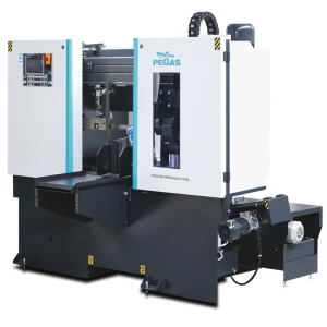
 300x300 HERKULES X-CNC / Herkules

| mm | 0° | 45° | 60° | -45° | -60° |  |
 |
|---|---|---|---|---|---|---|---|
 |
300 | x | x | x | x | x | x |
 |
300x300 | x | x | x | x | 300x220 |
 |
 |
 |
 |
 |
|---|---|---|---|---|
| 3x400V | 3,0 | 20-100 | 4520x34x1,1 | 1420 |
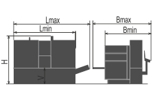
| Lmin | Lmax | Bmin | Bmax | Hmin | Hmax | V |
|---|---|---|---|---|---|---|
| 2230 | 2510 | 1450 | 2280 | 1800 | 800 |
- It is a highly efficient automatic hydraulically controlled band-saw with multiple material feed.
- The saw has extreme robust construction, in connection with powerfull blade of 34 mm width the machine ensures maximal perfomance.
- The machine is designed for vertical
- The machine is designed to saw steel materials, but also non-ferrous and light metals. However, we recommend consulting the manufacturer about this option.
- No other materials may be sawn without approval from the manufacturer.
Control system:
- Machine is equiped with programmable PLC SiEMENS SIMATIC S7-1200. Drive of band blade, movement of arm and movement of feeder are completely controlled and drive by SIEMENS technology.
- The coloured touch screen HMI SIEMENS TP 700 COMFORT enables easy communication with an operator. It shows working conditions (blade speed, moving to the cut, cutting parameters etc.)
- The machine enables to work with two modes:
- SEMIAUTOMATIC CYCLE: The machine cuts the material immediatelly in a semiautomatic mode. The operator uses the feeder of the machine for the manipulation with the material and for the exact feed of the material into the cutting zone. The movement of the feeder is realized by manual buttons or by GTO function. After starting GTO function the operator sets the position of the feeder, presses START GTO button and feeder goes to the set position.
- AUTOMATIC CYCLE: the feeder feeds the material according to the set programm. The operator sets the cutting programm, machine realizes these programms, it is possible to make thousand different programms.The part of one programm is a complete setting of the cut: blade speed, feed speed, setting of an automatic regulation, setting of the hight of the bar to be cut, setting of the lenght of the bar, angles values and number of pieces. The lenght and number of pieces it is possible to set in 20 lines, the machine feeds differently set lenghts automatically.
- Regulation of cutting feed is realized by controlled system by the servo-motor and throttle valve of hydraulic. Then is reached very precise cutting feed. Operator will input into program requiered cutting feed (mm/min) and bandsaw this cutting feed precisely set.
- Two basic regimes of automatic system regulation (ASR): ARP a RZP.
- RZP = Zone regulation. System enable to cut material in 5 zones, because of setting optional cutting feed and blade speed according on blade position.
- ARP = System of the automatic regulation of the cutting feed rate depending on the cutting resistance of the material or blunting the blade. Systém offers two basic modes of ARP: BIMETAL and CARBIDE.
- BIMETAL mode is suitable for optimalization of the cutting feed when cutting profiles by bimetal blades. The cutting feed is higher if the blade cuts sides of the profile. As the blade reaches the full material, the system reduces the cutting feed automatically so that teeth gap of the blade would not be filled.
- CARBIDE mode is suitable for cutting of full bars. If the blade is old (blunt), loaded is the cutting feed reduced Reaction time is slower than in mode BIMETAL.
- KKR= check of cut perpendicularity.. Directional system measure vertical position of band blade. If cutting feed is too fast, then bandsaw automatically reduced feed and wait until band blade get into optional position. When blade go back into optional position then system automatically increase cutting feed.
- The control panel is placed in the tightening pulley cover. The control panel is equiped with mechanical buttons and digital display of the machine control system. Mechanical buttons controls basic saw movements (arm, vice, feeder) and cutting cycle start. The safety button is present on the panel aswell. Buttons for controlling the movements of the machine are part of a high-quality foil keyboard.
- Safety module with autodiagnostics.
Construction:
- The machine is constructionaly designed in that way, so that it corresponds to extreme exertions in productive conditions. Massive construction enables using of carbid blades comfortably.
- The arm of machine with columns situated as near the clamping vice as possible minimizes vibrations and enables max. cutting performance.
- The arm of the machine is robust, heavy weldment and it is designed so that a toughtness and a precision of cut was ensured.
- The arm moves along two columns using a four row linear leading with a high loading capacity. Arm movement using hydraulic cylinder.
- Drive pulley and tighten pulley are both metal castings.
- Upper position automatically using: a) Pegas DPP system (touching lath placed closely below tooth of blade: T-bar, linear leading, microswitch, adjusting screw), b) using of incremental sensor for measuring of a position above material. Upper working position of the arm is possible to set in control system.
- Down working position is set with adjustable mechanical stop and microswitch. Down working position of the arm is also possible to set in the saw control system. After reaching bottom working position the arm stops in the position set in the system.
- Main vice with divided jaw that clamps the material in front of as well as behind the cut. The jaws allow a safe grip.The optimalization of the chip movement through the fixed jaw directly to the chip extractor.
- Jaws of the main vice move in steel leading using hydraulic cylinder. One jaw is longstroke (the movement by longstroke hydraulic cylinder), one is fixed.
- Regulation valves for setting a vice pressure in hydraulic system.
- Very massive feeder with the feeding step 500 mm moves using hydraulic cylinder and two sparpened bars and teflon cases.
- Incrementally straight sensor for indication of the position of the feeder. The position of feeder is displayed on the control system display. Feeder can have multiple feeding possibility.
- GTO function includes functions ABS, REL a ATB.
- Indication of material in the feeder: optic sensor - it notices that there is a material in the feeder. If there is no material in the feeder, the signal reflects on the glass that is situated on movable jaw and it goes back to the sensor. The machine stops feeding and waits for another bar.
- There is a roller conveyer which supports material in whole feeded lenght.
- The feeder clamping vice is a robust steel weldment. Jaws ensure safe clamping of the material.
- Jaws of the feeding vice move in steel leading using hydraulic cylinder. One jaw is longstroke (the movement by longstroke hydraulic cylinder), one is fixed.
- Cutting zone is opened from side of the feeder device automatically, extends the blade lifetime when arm is moving to top position.
- The blade leading in guides with hardmetal plates and leading bearings and along cast iron pulleys.
- There is a guide situated on the firm beam on the drive side. On the tightening side there is the guide situated on the moving beam.
- The guide beams of the blade are adjustable in the whole working range. A giude moving is connected with a vice-jaw movement so that to achieve the minimum distance of the guide and material. That is why it is not neccessary to set the position manually.
- The guide beam of the blade is placed in wide linear rails with high bearing capacity.
- The saw-band is equipped with a guard, which protects the operator from millings and cutting emulsion.
- Hydraulic tightening of band.
- Automatic indication of blade tension.
- A cleaning brush is driven by hydromotor and ensures perfect cleaning of a blade.
- Drive of machine is solved by worm gear box with maintenanceless oil filling. Three-phases electromotor with double winding, with a frequency converter for a fluent regulation of the blade speed from 20 to 100 m/min. Sturdy flange with shaft. Termoprotection of engine.
- The cooling system for emulsion, leaded to the guides of the blade and by LocLine system directly to the cut groove.
- Massive base with a tank for chips and with chip extractors. Base is designed for manipulation manipulation with machine by pallet truck and also by any hight lift truck.
- Indication of blade tightening and opening of the cover.
- Controlling 24 V.
- Machine is equipped with hydraulic system which controles all functions of that maschine. It pushes the arm to cut, pulls up the arm, opens and closes vices, moving of feeder.
Basic equipment of machine:
- Slide of cut pieces.
- Chip extractor
- Lighting of workink space.
- Band saw blade.
- Set of spanners for common service.
- Manual instructions in eletronic form (CD).
Operating cycle:
After starting the machine, vices clamp after starting the machine, the machine makes the cut by a set speed, the cutting zone in the down position of the arm is released - the longstroke jaw of the firm vice open, the feeder moves the material to the firm vice, the arm lifts up to the set upper position. The material is moved by the feeder – periodic regime (feeder moves between zero position and the position of the set lenght of feed) or consecutive regime (feeder moves to the limit position and clamps the material and feed it to the cut consecutively). The main vice clamps the material, the vice of the feeder is still closed and the whole procedure repeats. The operator only loads the material and removes the cut material. It is possible to regulate the cutting speed of the arm and the blade speed during cutting.
or send inquiry!