Double-column band saw machines for bundle cutting ->
Profi ->
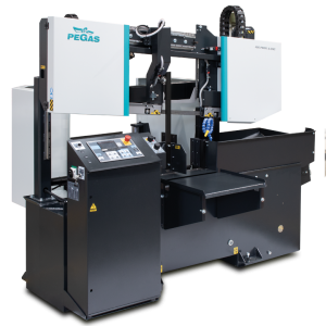
400 PROFI A-CNC
 400 PROFI A-CNC / Profi

| mm | 0° | 45° | 60° | -45° | -60° |  |
 |
|---|---|---|---|---|---|---|---|
 |
400 | x | x | x | x | x | x |
 |
400x400 | x | x | x | x | 400x340 | 400x350 |
 |
 |
 |
 |
 |
|---|---|---|---|---|
| 3x400V | 3,0 | 20-100 | 4520x34x1,1 | 1300 |
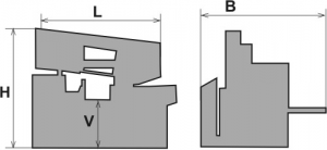
| Lmin | Lmax | Bmin | Bmax | Hmin | Hmax | V |
|---|---|---|---|---|---|---|
| 2525 | 2525 | 1530 | 2150 | 1867 | 2250 | 800 |
- It is a highly efficient automatic hydraulically controlled band-saw with multiple material feed.
- The machine has massive design, it is robust and has new conception of friendly control system.
- The blade is sloped 7 degrees to cutting table, which enables better performance during cutting of profiles as well as full materials and enables long lifetime of blade. These parameters together with powerfull drive and blade 34 mm heigh enable high productivity of machine.
- The machine is designed for vertical cuts.
- It is suitable for serial production in industrial premises.
- The machine is designed to saw steel materials, but also non-ferrous and light metals. However, we recommend consulting the manufacturer about this option.
- No other materials may be sawn without approval from the manufacturer.
Control system:
- It is a highly efficient automatic hydraulically controlled band-saw with multiple material feed.
- The machine has massive design, it is robust and has new conception of friendly control system.
- The blade is sloped 7 degrees to cutting table, which enables better performance during cutting of profiles as well as full materials and enables long lifetime of blade. These parameters together with powerfull drive and blade 34 mm heigh enable high productivity of machine.
- The machine is designed for vertical cuts.
- It is suitable for serial production in industrial premises.
- The machine is designed to saw steel materials, but also non-ferrous and light metals. However, we recommend consulting the manufacturer about this option.
- No other materials may be sawn without approval from the manufacturer.
Construction:
- The machine is constructionaly designed in that way, so that it corresponds to extreme exertions in productive conditions.
- The arm of machine with columns situated as near the clamping vice as possible minimizes vibrations and enables max. cutting performance.
- The arm of the machine is robust, heavy weldment and it is designed so that a toughtness and a precision of cut was ensured.
- Arm moves on two columns by a help of a four row linear leading with a high loading capacity. Moving of arm using one hydraulic cylinder.
- Regulation of cutting pressure RTR, which enables more efficient of profile materials cutting, longer blade life included
- Drive pulley and tighten pulley are both metal castings.
- Upper position automatically using Pegas DPP system (touching lath placed closely below tooth of blade: T-bar, linear leading, microswitch, adjusting screw)
- Down working position is set with adjustable mechanical stop and microswitch. Down working position of the arm is also possible to set in the saw control system. After reaching bottom working position the arm stops in the position set in the system.
- Main vice with divided jaw that clamps the material in front of as well as behind the cut. The jaws allow a safe grip.The optimalization of the chip movement through the fixed jaw directly to the chip extractor.
- Jaws of the main vice move in steel leading using hydraulic cylinder. One jaw is longstroke (the movement by longstroke hydraulic cylinder), one is fixed.
- Regulation valves for setting a vice pressure in hydraulic system.
- Very massive feeder moves using hydraulic cylinder and two sparpened bars and teflon cases.
- Placement of feeder movment is floating – it does mean feeder vice can movecouple of mm from side to side and eliminate potential unevenness of material.
- Feeder moves cutted material to cut zone follows adjusted value (operator set it with control panel). Feeder position is scanned using electromagnetic sensor and magnetic tape. Feeder moves to set positions using microfeeding (it enables accurate position of cutted material.)
- Indication of material in the feeder: optic sensor - it notices that there is a material in the feeder. If there is no material in the feeder, the signal reflects on the glass that is situated on movable jaw and it goes back to the sensor. The machine stops feeding and waits for another bar.
- The feeder clamping vice is a robust steel weldment. Jaws ensure safe clamping of the material.
- Jaws of the feeding vice move in steel leading using hydraulic cylinder. One jaw is longstroke (the movement by longstroke hydraulic cylinder), one is fixed.
- The blade leading in guides with hardmetal plates and leading bearings and along cast iron pulleys.
- The blade is 7 grades sloped regarding the level of the vice => higher performance when cutting, profiles, longer bladelife, higher performance when cutting full materials.
- There is a guide situated on the firm beam on the drive side. On the tightening side there is the guide situated on the moving beam.
- The guide beams of the blade are adjustable in the whole working range. A giude moving is connected with a vice-jaw movement so that to achieve the minimum distance of the guide and material. That is why it is not neccessary to set the position manually.
- The saw-band is equipped with a guard, which protects the operator from millings and cutting emulsion.
- Automatic indication of blade tension.
- Hydraulic tightening of band.
- Cleaning brush is driven by movement of pulley and enables high quality cleaning of blade. Driven cleaning brush is able as option 410-ECK (650 rev/min).
- Drive of machine is solved by worm gear box with maintenanceless oil filling. Three-phases electromotor with double winding, with a frequency converter for a fluent regulation of the blade speed from 20 to 100 m/min. Sturdy flange with shaft. Termoprotection of engine.
- The cooling system for emulsion, leaded to the guides of the blade and by LocLine system directly to the cut groove.
- Massive base with a tank for chips and with chip extractors. Base is designed for manipulation manipulation with machine by pallet truck and also by any hight lift truck.
- Indication of blade tightening and opening of the cover.
- Controlling 24 V.
- Machine is equipped with hydraulic system which controles all functions of that maschine. It pushes the arm to cut, pulls up the arm, opens and closes vices, moving of feeder.
Basic equipment of machine:
- Slide of cut pieces.
- Chip extractor
- Lighting of workink space.
- Band saw blade.
- Set of spanners for common service.
- Manual instructions in eletronic form (CD).
Operating cycle:
After start of the cutting machine clamp the vices, the cut will be done by ste speed. After reaching the down position, arm is going up automaticaly. Feeder move with next peace to the cuting zone (feeder vice is going between zero position and set position (length of cutted peaces). Main vice clamps the material, feeder vice is opening and moves to feed next peace. Whole cyclus starts again. Operator puts new material and remove cutted peaces only. It is possible change blade speed as well as shift speed during the cut.
Do you like this?
Contact us
or send inquiry!
or send inquiry!