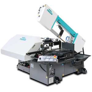
 360x500 A-CNC-R / Automatic band saw machine

| mm | 0° | 45° | 60° | -45° | -60° |  |
 |
|---|---|---|---|---|---|---|---|
 |
360 | 360 | 300 | x | x | x | x |
 |
500x360 | 440x240 | 290x280 | x | x | 500x220 | 300x160 |
 |
500x360 | 400x340 | 270x340 | x | x | 270x340 | 300x160 |
 |
 |
 |
 |
 |
|---|---|---|---|---|
| 3x400V | 3,0 | 20-100 | 4780x34x1,1 | 1500 |
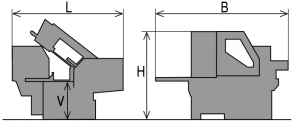
| Lmin | Lmax | Bmin | Bmax | Hmin | Hmax | V |
|---|---|---|---|---|---|---|
| 2165 | 2940 | 2580 | 2600 | 1455 | 2340 | 800 |
- It is a highly efficient automatic hydraulically controlled band-saw with multiple material feed.
- The machine is designed for vertical and angular cuts.
- Angles setting (turning of the bow) manualy:
- fluently between 0° and +45°right in automatic mode
- fluently between 0° and +60°right in semi-automatic mode
- The machine is designed to saw steel materials, but also non-ferrous and light metals.
However, we recommend consulting the manufacturer about this option.
Control system:
- Machine is equipped with the programmable PLC MITSUBISHI FX5U.
- Blade drive as well as the feeder movements afe fully controlled by the frequency inverters MITSUBISHI.
- The colour touch screen MITSUBISHI GT 2104 for easy communication with an operator. It shows working conditions (blade speed, feed to the cut, cutting parameters etc.)
- The lenght and quantity are set by the control panel. Machine will optimize all next calculations itself. It is possible to set 20 different programms.
- Type of material feed: Normal or INCREMENTAL
- Machine enables semi-automatic and automatic mode (all movements are controlled automatically).
- Regulation of cutting feed is manual and uses valve placed beside control panel. Automatic (safety) regulation of shift speed PEGAS BRP. Principle: Machine will stop after exceeding set motor load (defined in ampers).
- The ergonomical control panel is mounted on the movable console. The control panel is equiped with mechanical buttons and digital display of the machine control system. Mechanical buttons controls basic saw movements (frame, vice, feeder) and cutting cycle start. The safety button is located on the panel aswell. Buttons for controlling the movements of the machine are part of a high-quality foil keyboard.
Construction:
- The machine is constructionaly designed in that way, so that it corresponds to extreme exertions in industrial conditions.
- The frame of the machine is robust, heavy weldment and it is designed so that a toughtness and a precision of cut was ensured.
- The frame is situated in pretightened slide bushes with a teflon friction surface.
- Drive pulley and tightening wheels are both metal castings.
- Movement of the frame is controlled with buttons on control console.
- Up and bottom position are set by control system. Function of the blade and frame movement are possible to set in machine parameters.
- Vise is weldement with jaws made from casted iron. The jaws ensure secure firm clamping of the material.
- Jaws of the main vice move in steel leading.
- Moving jaw of the vice is handled by long stroke hydraulic cylinder.
- Very rigid feeder is moving on two linear leadings with step 990 mm and is placed on the basement with support rollers by the linear leading.
- Movement of the feeder is ensured by ballscrew which is powered by electromotor with encoder and frequency inverter. Transmission between the ballscrew and the electro motor is solved by gear belt (nut of the ballscrew is mounted on the feeder)
- The position of the feeder is detected using the rotating encoder. For maximaly precise feeding the feeder is going from near position to the set position by micromovement. Accelerating and decelerating is controlled by frequency inverter.
- There is a floating seating of the feeding vice in the feeder, it means that the feeding vice moves in perpendicular sense regarding the feeding direction. The stationary jaw of the feeding vice copies the possible roughness of feeded material and the worning out of mechanical parts of the feeder is eliminated.
- The feeder moves the material to main vise by the lenght set in the control system. For a material feeding function ABS or REL can be used. For precise feeding the machine goes to its position by micromovement.
- Indication of material in the feeder: optical sensor detects that there is a material in the feeder. If there is no material in the feeder, the signal is reflected to the sensor by the glass that is situated on movable jaw. The machine stops feeding and waits for another bar.
- The feeder clamping vice is made from cast iron. Jaws ensure safe clamping of the material.
- Hydraulicaly controlled vice of the feeder. Stroke of vice in whole width via long-stroke hydraulic cylinder.
- The turntable is casted iron, set on tapered roller bearings.
- Manuall turning of the table for angle cuts, the position of the turntable is fixed by the lever with the excenter.
- Angles (degrees are shown at the touch screen MITSUBISHI. Angle indication using incremental sensor and a magnetic tape.
Basic equipment of machine:
- The blade leading in guides with hardmetal plates and leading bearings, along cast iron wheels.
- There is a guide situated on the firm beam on the drive side. On the tightening side there is the guide situated on the moving beam.
- The guide beam of moving blade guide is adjustable. Manual adjustment and fixing of the guide beam.
- Guide holder moves in adjustabled dovetail groove.
- The blade is equipped with a cover, which protects the operator from chips and cutting emulsion.
- Mechanical tightening of the blade.
- Automatic indication of blade tension.
- A cleaning brush for perfect cleaning and function of blade, passive driven by pulley.
- Drive of machine is solved by worm gear box with maintenanceless oil filling. Three-phases electromotor with double winding, with a frequency converter for a fluent regulation of the blade speed from 20 to 100 m/min. Sturdy flange with shaft. Thermal protection of motor.
- The cooling system for emulsion, leaded to the blade guides.
- Massive base with a box for chips. Base is designed for manipulation with machine by pallet truck and also by forklift truck.
- Indication of blade tightening and opening of the cover by microswitch circuit.
- Control 24 V.
Basic accessories of machine:
- Band saw blade.
- Set of spanners for common service .
- Manual instructions in eletronic form (CD).
Operating cycle:
The saw automaticaly clamps the material in main vise and feeder is moved to set position. The frame goes to the cut by quickshift and after reaching the upper working position the speed is automatically set to working speed. After the material is cut the frame goes up to the upper working position. The feeder moves by the added lenght and the feeder vise clamps the material. Main vise then opens and material is feeded to the set lenght, then the material is clamped by the main vise and whole cycle is repeated. An operator only manipulates with the material. It is possible to adjust the speed of the blade and feed to the cut during the cutting.
or send inquiry!