 440x600 HORIZONTAL X-NC-2000 / Horizont
 It's no longer on sale
| mm | 0° | 45° | 60° | -45° | -60° |  |
 |
|---|---|---|---|---|---|---|---|
 |
470 | 475 | 330 | 475 | 305 | x | x |
 |
250* | 180* | 130* | 180* | 130* | x | x |
 |
610x410 | 490x415 | 320x410 | 495x415 | 305x425 | 610x255 |
 |
 |
 |
 |
 |
|---|---|---|---|---|
| 3x400V | 4,0 | 20-100 | 6060x34x1,1 | 3835 |
| Lmin | Lmax | Bmin | Bmax | Hmin | Hmax | V |
|---|---|---|---|---|---|---|
| 2950 | 3500 | 4600 | 2140 | 2220 | 810 |
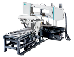
It is a highly efficient automatic hydraulically controlled band-saw with multiple material feed.
The band saw machine is designed for cutting in semiautomatic cycle perpendicularly as well as angularly. It enables angle cuts to the left (60 grades) and to the right (60 grades).
The band saw machine suitable for cutting of steel constructions and profiles with a longstep feeder L=2000mm. The machine is constructed for automatic cutting of long bars. Whenn the machine is cutting Automatic programm with angle cuts and with lenghts shorter thann (500mm), the machine automatically interrupts the automatic cycle and is waiting.
It is suitable for serial production and thanks to its robust construction enables to cut wide range of materials including stainless steels and tool steels both profiles and full materials.
Control system:
- Machine is equiped with programmable PLC SiEMENS SIMATIC S7-1200. Drive of band blade, movement of arm and movement of feeder are completely controlled and drive by SIEMENS technology.
- The coloured touch screen HMI SIEMENS TP 700 COMFORT enables easy communication with an operator. It shows working conditions (blade speed, moving to the cut, cutting parameters etc.)
- The machine enables to work with two modes:
- SEMIAUTOMATIC CYCLE: The machine cuts the material immediatelly in a semiautomatic mode. The operator uses the feeder of the machine for the manipulation with the material and for the exact feed of the material into the cutting zone. The movement of the feeder is realized by manual buttons or by GTO function. After starting GTO function the operator sets the position of the feeder, presses START GTO button and feeder goes to the set position.
- AUTOMATIC CYCLE: the feeder feeds the material according to the set programm. The operator sets the cutting programm, machine realizes these programms, it is possible to make thousand different programms.The part of one programm is a complete setting of the cut: blade speed, feed speed, setting of an automatic regulation, setting of the hight of the bar to be cut, setting of the lenght of the bar, angles values and number of pieces. The lenght and number of pieces it is possible to set in 20 lines, the machine feeds differently set lenghts automatically.
- Bandsaw is using ATB system=automatic transport of new bar exactly to cutting zone. Operator of bandsaw doesn´t need to cut the face off. Minimizes time and costs
- Regulation of cutting feed is realized by controlled system by the servo-motor and throttle valve of hydraulic. Then is reached very precise cutting feed. Operator will input into program requiered cutting feed (mm/min) and bandsaw this cutting feed precisely set.
- Two basic regimes of automatic system regulation (ASR): ARP a RZP.
- RZP = Zone regulation. System enable to cut material in 5 zones, because of setting optional cutting feed and blade speed according on blade position. Operator can choose from 2 strategy settings: DEFENSIVE setting is approppriate for cutting very hard materials with use of carbide band blade. Cutting feed is in beginning and in the end reduced. OFENSIVE settings supports executive cutting logs. Cutting feed and band speed are in the beginning and in the end of cut increased. It´s about similar principle as ARP mode. Advantage is regulation of blade speed.
- ARP = System of the automatic regulation of the cutting feed rate depending on the cutting resistance of the material or blunting the blade. Systém offers two basic modes of ARP: BIMETAL and CARBIDE.
- BIMETAL mode is suitable for optimalization of the cutting feed when cutting profiles by bimetal blades. The cutting feed is higher if the blade cuts sides of the profile. As the blade reaches the full material, the system reduces the cutting feed automatically so that teeth gap of the blade would not be filled.
- CARBIDE mode is suitable for cutting of full bars. If the blade is old (blunt), loaded is the cutting feed reduced Reaction time is slower than in mode BIMETAL.
- RTO function (rotate to position) with automatic setting of needed angle arm position.
- The ergonomical control panel is mounted on the movable console and its position does not depend on the turntable position at any angle. The control of the machine is optimalized with our control panel and the field of view is better for an operator. The control panel is equiped with mechanical buttons and digital display of the machine control system. Mechanical buttons controls basic saw movements (arm, vice, feeder and turntable movements) and cutting cycle start. The safety button is present on the panel aswell. All buttons are highly resistant in anti-vandal version.
- Safety module with autodiagnostics.
Construction:
- The machine is constructionaly designed in that way, so that it corresponds to extreme exertions in productive conditions. A robust construction of machine includes vice allows to take advantage of bimetal blades maximally.
- The arm of the machine is robust, heavy weldment and it is designed so that a toughtness and a precision of cut was ensured.
- The arm moves along two columns using a four row linear leading with a high loading capacity. Arm movement using two hydraulic cylinders.
- Drive pulley and tighten pulley are both metal castings.
- Arm uses the incremental encoder and the magnetic tape to evaluate a position over material and an end stop for setting the down position.
-
- optimalization of the chip movement through the fixed jaw directly to the chip extractor.
- Jaws of the main vice move in steel leading using hydraulic cylinder. One jaw is longstroke (the movement by longstroke hydraulic cylinder), one is fixed.
- Regulation valves for setting a vice pressure in hydraulic system.
- Very rigid feeder is placed on the basement with rollers by the linear leading
- Feed step 2000mm, Multiple feed ( max. lenght 30m)
- Transporter is driven by by electromotor and conical gearbox, transmission by toothed wheel and toothed bar, frequency convertor.
- The feeder moves the material to be cut to the main vice according to the set lenght that was adjusted by the operator in the controlling panel. The position of the feeder is indicated by incremental encoder.
- Operator choose one from 5 feeder speeds.
- Indication of material in the feeder: optic sensor - it notices that there is a material in the feeder. If there is no material in the feeder, the signal reflects on the glass that is situated on movable jaw and it goes back to the sensor. The machine stops feeding and waits for another bar.
- There is a roller conveyer which supports material.
- The feeder clamping vice is a robust steel weldment. Jaws ensure safe clamping of the material.
- Jaws move on two rails of linear system thanks to hydraulic cylinder. One jaw is longstroke (the movement by longstroke hydraulic cylinder). Second jaw is fixed.
- Turn table is massive weldment. Turn table for angular cutts with milled leading parts of base. Turn table enables comfortable claming of cutted material.
- Turning of the table for angle cuts is ensured by the hydraulic cylinder and the rack and pinion gear, hydraulic fixing at turn. RoTo function (rotate to position) with the automatic setting of the desired position.Main vice with divided jaw that clamps the material in front of as well as behind the cut. The jaws allow a safe grip.The
- The angles indicated on the digital display on the control panel. Reading of angle by incremental sensor and magnetic tape.
Basic equipment of machine:
- The blade leading in guides with hardmetal plates and leading bearings and along cast iron pulleys.
- The blade is sloped regarding the level of the vice => higher performance when cutting, profiles, longer bladelife, higher performance when cutting full materials.
- There is a guide situated on the firm beam on the drive side. On the tightening side there is the guide situated on the moving beam.
- The guide beams of the blade are adjustable in the whole working range. A giude moving is connected with a vice-jaw movement so that to achieve the minimum distance of the guide and material. That is why it is not neccessary to set the position manually.
- The guide beam of the blade is placed in linear rails (2 linear rails and 4 bearings) with high bearing capacity.
- The saw-band is equipped with a guard, which protects the operator from millings and cutting emulsion.
- Hydraulic tightening of band.
- Automatic indication of blade tension.
- A passive driven cleaning brush for perfect cleaning and function of blade by roller.
- Pulley drive the saw blade is solved by worm gear box with maintenanceless oil filling. Three-phases electromotor with double winding, with a frequency converter for a fluent regulation of the blade speed from 20 to 100 m/min. Sturdy flange with shaft. Termoprotection of engine.
- The cooling system for emulsion, leaded to the guides of the blade and by LocLine system directly to the cut groove.
- Massive base with a tank for chips. Base is designed for manipulation manipulation with machine by pallet truck and also by any hight lift truck or by crane.
- Indication of blade tightening and opening of the cover.
- Controlling 24 V.
- Machine is equipped with hydraulic system which controles all functions of the machine. It pushes the arm to cut, pulls up the arm, opens and closes vices, turnins the turntable for angular cuts.
Basic accessories of machine:
- RTS- pressure control vice
- Two massive cylinders support material to be cut. Movable by linear leading. Placement at the output side.
- Spray gun for chip rinsing
- Lighting of workink space.
- Band saw blade.
- Set of spanners for common service.
- Manual instructions in eletronic form (CD).
Operating cycle:
After starting the machine, vices clamp after starting the machine, the machine makes the cut by a set speed, the cutting zone in the down position of the arm is released - the longstroke jaw of the firm vice open, the feeder moves the material to the firm vice, the arm lifts up to the set upper position. The material is moved by the feeder – periodic regime (feeder moves between zero position and the position of the set lenght of feed) or consecutive regime (feeder moves to the limit position and clamps the material and feed it to the cut consecutively). The main vice clamps the material, the vice of the feeder is still closed and the whole procedure repeats. The operator only loads the material and removes the cut material. It is possible to regulate the cutting speed of the arm and the blade speed during cutting.
| Code | Description | Type |
|---|
Tech. data NO241 are valid on 1.1.2024. Producer has the right to make changes of technical data.
Values contained on this page are only for information purposes. This information is not an offer and is not a public promise. This indicative offer does not give right to close a contract. The only guiding document for the contract is a valid price list.